
***************************************************************************************************************************************************
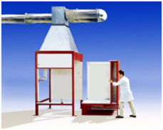
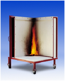
Single Burning Item ( EN 13823)
WHAT IS THE SBI TEST? The Single Burning Item (SBI), is a method of test for determining the reaction to fire behaviour of building products (excluding floorings) when exposed to the thermal attack by a single burning item (a sand-box burner supplied with propane). The specimen is mounted on a trolley that is positioned in a frame beneath an exhaust system. The reaction of the specimen to the burner is monitored instrumentally and visually. Heat and smoke release rates are measured instrumentally and physical characteristics are assessed by observation .
WHY IS THE SBI SO IMPORTANT? Most construction products sold in Europe will shortly need to be tested and classified using a new test method called the Single Burning Item (the SBI) EN 13823. The construction products directive of the European commission will require that all European Member states eventually use this, instead of the traditional regulatory methods used in each country, to classify most building products. The Commission recently defined the criteria for assessing building products into classes A-F. These are given in the table below. Though other test methods are required the SBI is needed to classify all non flooring products into the classes A2, B, C and D which are the major classes inhabited by most products other than those that are principally inorganic classified as non-combustible .
HOW IS THE SBI USED TO CLASSIFY COMBUSTION PRODUCTS?
Class |
Criteria for compliance |
Other classification |
Other Test Method(s) |
A2 |
FIGRA < 120W/s; and |
Smoke production |
EN ISO 1182 or EN ISO 1716 |
B |
FIGRA < 120W/s; and |
Smoke production |
EN ISO 11925-2 |
C |
FIGRA < 250W/s; and |
Smoke production |
EN ISO 11925-2 |
D |
FIGRA < 750W/s |
|
EN ISO 11925-2 |
Non-Combustibility Apparatus
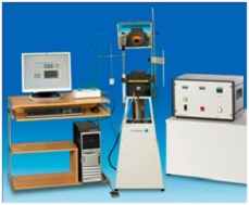
EN ISO 1182 - IMO FTPC Part 1 - ASTM E 2652 The FTT EN ISO 1182 (IMO FTPC Part 1, ASTM E 2652) system has been designed with significant new features. Rather than the traditional variac control, where it is possible to supply too high a current to the heater element during the heating cycle, FTT has automated this process by using modern electronics. The benefits of this system over traditional variac systems, which considerably extend the life of the furnace, are:
• soft start
• ramp rate
• power limit
• over temperature device .
The FTT ISO 1182 apparatus consists of the following:
SPECIAL TUBE FURNACE
Manufactured from steel with a polished finish. This single zone furnace has a maximum operating temperature of 900°C. The furnace is easily replaceable during maintenance and servicing procedures.
INSTRUMENTATION
A 19" instrument case houses all the instrumentation. This unit features a temperature controller, an over-temperature alarm and a power controller, which controls the furnace temperature at 750°C, compensating for supply voltage fluctuations and displaying the power (Watts) being supplied to the furnace.
SOFTWARE (NonComb)
The software is a Microsoft Windows based application with simple push button actions, data entry fields, check boxes and other standard Windows operations.
The operator can monitor temperatures on a Status panel, before performing a test, without recording any data. Before a test, the specimen information (material name, density, mass, laboratory name, etc.) is entered into the computer and saved to a file.
During a test, the temperature of the furnace, specimen surface and specimen centre thermocouples are recorded at a rate of 2 Hz (i.e. every 0.5 seconds) and the temperatures displayed on a graph in real time. Also the initial, maximum and final temperatures recorded by the three thermocouples are displayed during the test run.
After the test, the user is prompted to enter any comments about the material performance, the total time of sustained flaming and the final mass. The appropriate temperature rises are calculated and then a report for the test specimen can be generated.
The test report shows the material information, the initial, maximum and final temperatures, the required temperature rises, the total flaming time, the mass loss (actual and as a percentage of the initial mass) and a graph of the recorded temperatures against time. The test report also includes a reference to the pass-fail criteria given in the appropriate Standards and states whether the specimen meets these criteria.
All the test data is saved to the hard disk as an ASCII file which can then be imported into spreadsheets for additional analysis .
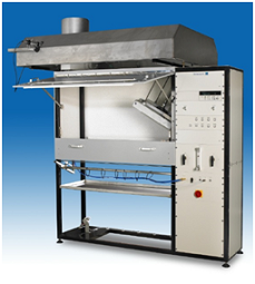
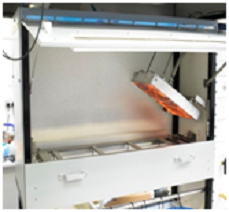
Flooring Radiant Panel Test Apparatus
EN ISO 9239-1, ASTM E 648, ASTM E 970, NFPA 253
This test method is used to measure the critical radiant flux of horizontally-mounted floor covering systems exposed to a flaming ignition source in a graded radiant heat environment, within a test chamber. It can also be used to measure this same critical radiant flux for exposed attic floor cellulose insulation.
The European Union is using this test method for fire classificaiton of flooring products, throughout European Member States.
The radiant heat is applied by means of a gas-fuelled panel, inclined at 30º, and directed at a horizontally mounted floor covering system specimen. The radiant panel generates a radiant energy flux distribution ranging from a nominal maximum of 10.9 kW/m2 to a minimum of 1.1 kW/m2.
A small stainless steel pilot burner assists in specimen ignition.
The distance burned until flame-out is reached and converted, by calibration, into an equivalent critical radiant flux, in kW/m2.
A smoke measuring system, according to DIN 50055, is mounted on a separate frame at the exhaust stack.
Traditionally, tests are conducted to give a maximum critical radiant heat flux of 10.9 kW/m2, but it can optionally be conducted with higher radiant heat input, of up to 25.0 kW/m2.
Features:
- Angled Control Rack for convenience in use, allowing observation of the apparatus and controls duing equipment set-up and calibration.
- Automatic ignition of the radiant panel and safety cut-out.
- Hinged access to test area, via 2 position door with observation window and sliding platform.
- Stainless steel hood with smoke measurement ports.
Data acquisition and analysis software.
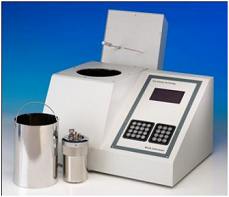
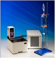
Bomb Calorimeter(EN ISO 1716)
The FTT EN ISO 1716 Bomb Calorimeter is an affordable high resolution isoperibolic temperature regulated oxygen bomb calorimeter with embedded control computer.
The bomb calorimeter is the most common device for measuring the heat of combustion or calorific value of a material. With this apparatus a test specimen of specified mass is burned under standardised conditions. The heat of combustion determined under these conditions is calculated on the basis of the observed temperature rise while taking account of heat loss. The combustion process is initiated inside an atmosphere of oxygen in a constant volume container, the bomb, which is a vessel built to withstand high pressures. It is immersed in a stirred water bath, and the whole device is the calorimeter vessel. The calorimeter vessel is also immersed in an outer water bath. The water temperature in the calorimeter vessel and that of the outer bath are both monitored.
The FTT Oxygen Bomb Calorimeter can be used to measure the heat generated from several applications and has been designed to conform to current ASTM, ISO, EN, BS and DIN international standards. The calorific value of the following groups of materials can be measured: -
- Building materials (e.g. EN ISO 1716)
- Coal, coke (e.g. ASTM D 5865)
- Fuel (gasoline, kerosene, fuel oil, No.s 1-D and 2-D diesel fuel and No.s 0-GT, 1-GT, and 2-GT gas turbines fuels), (e.g. ASTM D240-92)
- Hydrocarbon fuels (e.g. ASTM D 4809-90)
- Food, supplements, crops
- Waste and refuse
- Combustible materials, etc.
Isoperibolic Operating Mode
An isoperibolic bomb calorimeter is a calorimeter where the jacket temperature is kept at a constant temperature while the calorimeter vessel (bomb and bucket) temperature rises as heat is released by the combustion of a sample. The jacket and bucket temperatures are continuously measured enabling the heat loss to be corrected for after the test.
An embedded control computer, keypad and LCD enables instrument automation, data acquisition and analysis via user friendly menu driven software.
Automatic Temperature Control of Outer Bath
The embedded control computer automatically sets the outer bath temperature. The temperature is measured using two high precision, high resolution platinum resistance thermometers (PRTs). An external thermostatic controller, bath, circulator and cooler is supplied as standard together with a pipette for temperature controlled filling of the calorimeter vessel. This removes human error increasing repeatability and significantly reduces the preparation time between tests.
Oxygen Filling System
To simplify instrument operation the FTT Bomb Calorimeter is fitted with a semi-automatic filling system. The user merely connects the push on coupling and presses the key to fill the bomb with oxygen. The bomb then fills to the desired pressure and automatically switches off. If this pressure is not reached an error message is shown.
Automatic Firing
The embedded computer controls the temperature of the outer bath and shows when the calorimeter vessel temperature has stabilised. At this point the bomb is automatically fired.
Calibration
The FTT bomb calorimeter is calibrated by burning certified benzoic acid to determine a constant called the ‘water equivalent’. The instrument can record the water equivalent for several bomb/bucket combinations. For each bomb/bucket combination five calibrations are performed. The software calculates the average of these five calibrations and uses this value as the water equivalent when testing a sample.
Ordering Guide
The FTT Bomb Calorimeter consists of: -
Bomb calorimeter with embedded computer control, user-friendly interface, LCD graphics display, high accuracy / resolution PRTs, 2 x RS232 interfaces, parallel port for printer.
- Oxygen bomb and bucket (calorimeter vessel)
- Thermostatically controlled bath, circulator, cooler, pipette (2L)
- EN ISO 1716 sample preparation device, firing wire & cotton, cigarette paper
- Accessories for installation
Optional accessories: -
- Spare oxygen bomb
- Corrosion resistant oxygen bomb (corrosion resistant to halogen gases)
- Printer
- Bucket
- Benzoic acid, 100g
- Nickel Chrome Crucible
- Nickel Chromium Firing Wire 25m length
- Analytical Balance
- Firing cotton
Dimensions (LxWxH)
- FTT Bomb Calorimeter: 420 x 360 x 540mm
- Tank and controller: 350 x 325 x 355mm
- Cooling system: 460 x 305 x 225mm
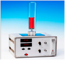
Oxygen Index
ASTM D 2863, BS ISO 4589-2, NES 714
The Oxygen Index is, perhaps, the most economical and precise quality control test of combustible materials. Its ease of use together with high levels of precision has made this technique a primary characterising and quality control tool to the plastic and electric cable industries and it has been specified by several military and transport groups. The technique measures the minimum percentage of oxygen in the test atmosphere that is required to marginally support combustion. Note that BS ISO 4589 supersedes BS 2782 Part 141.
The FTT unit has been designed to be compact for efficient use in a standard fume cupboard (or under a simple ventilation hood that we can also supply if required). The unit gives continuous digital readout of oxygen concentrations in the test atmosphere to facilitate quick settings of test concentration. Stabilised oxygen percentages are read from the digital readout and no additional flow adjustments are required. This is a considerable improvement over systems that use analogue gauges or require flow matching and the use of graphs or tables to calculate oxygen concentrations. This makes the unit as automatic as is feasible.
The Oxygen Index can be used in conjunction with the Elevated Temperature Oxygen Index apparatus (TOI) to determine the oxygen index at temperatures up to 125°C.
FEATURES
- New Paramagnetic Oxygen Cell for assessing accurate oxygen (< 0.1%) levels.
- Compact unit for efficient use inside a laboratory hood, with ventilation.
- Automatic flow control gives oxygen level adjustment by turning one single valve.
- Quick loading of test specimen into test chimney measuring 450 mm × 75 mm.
- Digital display of oxygen percentage in atmosphere during test (no calculations needed).
- Digital display of temperature of gas mixture entering the test chimney.
- Sample holders for both rigid and flexible samples supplied.
- Shortened gas path for rapid response
SPECIFICATION
- Digital readout for oxygen concentration: +/- 0.1%
- Dimensions (mm): 350(W) x 370(D) x 280(H)
- Column size (mm): 75 & 100(dia) x 450(H)
- Weight (kg): 14
- Voltage: 230V 50Hz 1A or 110V 60Hz 2A
- Operating Manual: Supplied
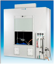
Horizontal/Vertical Flame Chamber
UL 94
The FTT UL 94 tests the flammability of plastic materials for parts in devices and appliances. The apparatus is supplied as a complete system incorporating all the features necessary for ease of use safety. It conforms to all five UL 94 horizontal and vertical burner tests and associated ASTM international standards. These are:
- Horizontal Burning Test; UL 94HB (ASTM D 635, IEC 60695-11-10, IEC 60707, ISO 1210).
- Vertical Burning Test: UL 94 V-0, V-1, or V-2 (ASTM D 3801, IEC 60695-11-10, IEC 60707, ISO 1210).
- 500 W (125mm) Vertical Burning Test: 5VA or 5VB (ASTM D 5048, IEC 60695-11-20, IEC 60707, ISO 9772).
- Thin Material Vertical Burning Test: VTM-0, VTM-1, or VTM-2 (ASTM D 4804, ISO 9773).
- Horizontal Burning Foamed Material Test: HF- 1, HF-2 or HBF (ASTM D 4986, ISO 9772).
Burners (ASTM D 5025, ASTM D 5207, ISO 10093, ISO 103351)
FEATURES
- A bench mounted draft free combustion chamber having a large inside volume of 1.0m3 and fitted with an interior light and exhaust fan to enable simple evacuation of combustion products
- Large door and window made from toughened safety glass giving a generous view of the specimen during a test.
- Specimen holders.
- Fully adjustable horizontal and vertical specimen supports.
- A burner in compliance with ASTM D 5025, with simple angle adjustment (0°, 20°, 45°) and precision gas control system including gas flow meter, pressure regulator and pressure gauge.
- Two access ports enabling easy entry to the chamber for movement of the burner and specimen.
- A burner wing tip.
- Three digital test duration timers for accurate but simplified operation
OPTION
Burner calibration kit, conforming to ASTM D 5207.
.
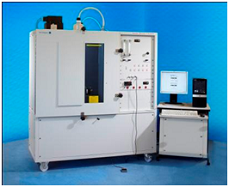
NBS Smoke Density Chamber
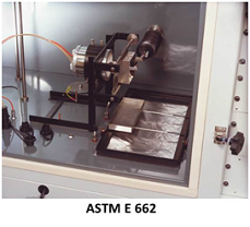
BS 6401, ASTM E 662, ASTM F814, NFPA 258
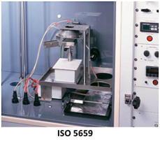
Options: ISO 5659/IMO FTPC Part 2, ATS 1000.001/ABD0031, NES 711
This instrument has been established for many years and is used widely in all industrial sectors for the determination of smoke generated by solid materials and assemblies mounted in the vertical position within a closed chamber.
This widely-used test instrument measures the specific optical density of smoke generated by materials when an essentially flat specimen, up to 25 mm thick, is exposed vertically to a radiant heat source of 25 kW/m2, in a closed chamber, with or without the use of a pilot flame.
- Test chamber with full width opening door, allowing easy access for sample loading and chamber cleaning.
- Controls are mounted beside chamber for convenient operation. They are not obstructed when door is open.
- Smoke density and temperature are on digital displays, for easier use and greater accuracy.
- Chamber walls are pre-heated for easier start-up and convenient equipment operation.
- Safety blow-out panel, easily replaceable, allows for safe operation of test method.
- Gas measurement ports are provided, for optional measurements of toxic gases.
- Cabinet designed with a standard 19" rack, for simple addition of gas analysers and chart recorder and other control units.
Computer software optionally available.
The FTT smoke chamber has been designed specifically for potential modification to incorporate the ISO 5659 Conical Radiant Furnace which extends the potential of the NBS Smoke Chamber by allowing variable heat fluxes (up to 50 kW/m2), horizontal orientation of the specimen and the measurement of mass loss rate of the specimen. This also conforms with the recent IMO test protocols.
Overall Specifications:
Size (m): 1.90 (H) x 1.63 (L),x 0.66 (D) Power Supply: 110/230 V - 50/60 Hz - 13 A
Size of actual chamber: 914 mm × 914 mm × 610 mm
.
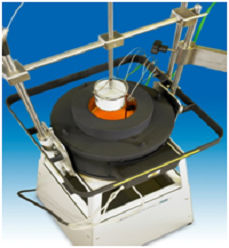
Cone Calorimeter
ISO 5660, ASTM E 1354, ASTM E 1474, ASTM E 1740, ASTM F 1550, ASTM D 6113, NFPA 264, CAN ULC 135, BS 476 Part 15
The Cone Calorimeter is the most significant bench scale instrument in the field of fire testing.
Heat release is the key measurement required to assess the fire development of materials and products. Traditionally it has been very difficult to measure and more recently full scale testing of items (e.g. furniture) has been possible by burning these articles and measuring the evolved heat using a technique called oxygen depletion calorimetry.
In the early 1980's workers at NIST (formerly NBS), in the USA, decided to produce an improved bench scale heat release test which would overcome the deficiencies of existing small scale heat release tests which relied on the measurement of the outflow enthalpy of enclosed systems. Oxygen depletion calorimetry was identified as the best measurement method. This is based on the empirical observation that heat released by burning materials is directly proportional to the quantity of oxygen used in the combustion process. The instrument was called a Cone Calorimeter. This name was derived from the shape of the truncated conical heater that is used to irradiate the test specimen with fluxes up to 100 kW/m2 in the test.
The FTT Cone Calorimeter has been produced to meet all existing Standards (including ISO 5660, ASTM E 1354, ASTM E 1474, ASTM E 1740, ASTM F 1550, ASTM D 6113, NFPA 264, CAN ULC 135 and BS 476 Part 15) and can also be purchased in modular form so that those laboratories with particular interests such as heat release, mass loss, smoke production, etc. can initially purchase the sections they require and later add further instrumentation into the same cabinets in order to complete a full specification instrument. This is just one of the advantages of the FTT Cone Calorimeter.
A full system consists of:
- Conical Heater - is wound in the form of a truncated cone, rated 5000 W at 230 V with a heat output of 100 kW/m2.
- Facility for testing horizontally or vertically orientated specimens
- Temperature control by the use of a 3 type K thermocouples and a 3-term (PID) temperature controller.
- A Split Shutter Mechanism - protects the sample area before the test. This ensures the initial mass measurement is stable and the operator has additional time for system checks before starting the test. This added time is very important for easily-ignitable samples, which often ignite prematurely if a shutter mechanism is not used.
- Specimen Holders - for specimens 100mm x 100mm up to 50mm thick, in the horizontal and vertical orientation.
- Load Cell - mass measurements are conducted via a strain gauge load cell with an accuracy of 0.01g. Fitted with a quick electronic tare facility and mechanical stops to avoid movement damage, give stable results and long life.
- Spark Ignition - by 10 kV spark generator fitted with a safety cut-out device. The igniter is automatically positioned by a lever linked with the shutter mechanism.
- Exhaust System - manufactured from stainless steel for long life. This comprises, hood, gas sampling ring probe, exhaust fan (with adjustable flow controls from 0-50g/s, at a resolution of at least 0.1g/s) and an orifice plate flow measurement (thermocouple and differential pressure transducer). Normal operation is at a nominal 24 l/s.
- Gas Sampling - comprising particulate filters, refrigerated cold trap, pump, drying columns and flow control.
- Oxygen Analysis - paramagnetic oxygen analyser, which has a range of 0-25% and a performance compliant with the standards.
- Smoke Obscuration - measured with a laser system, using photodiodes, and a 0.5 mW Helium Neon laser, with main and reference (compensating) photo detectors. Supplied with alignment cradle and 0.3, 0.8 neutral density filters for calibration.
- Heat Flux Meter - for setting the irradiance level at the surface of the specimens.
- Calibration Burner - to calibrate the rate of heat release measured by the apparatus using methane of 99.5% purity.
- Data Acquisition – Agilent Data Acquisition / Switch Unit featuring a 3-slot cardcage with 6½ digit (22 bit) internal DMM enabling up to 120 single-ended or 48 double-ended measurements. Scan rates up to 250 channels/s are available with a 115kbaud RS232 and PCI GPIB interface as standard. All readings are automatically time stamped and can be stored in a non-volatile 50,000-reading memory.
- FTT ConeCalc Software – it is available in multi-languages including English, French, German, Spanish and Japanese. The user interface is a Microsoft Windows based system with “user friendly” push button actions and standard Windows data entry fields, drop down selectors, check boxes and switches capable of:-
- Showing the status of the instrument
- Calibrating the instrument and storage of calibration results
- Collecting data generated during a test
- Calculating the required parameters
- Presenting the results in a manner approved by the Standards
- Averaging of multiple tests
- Exporting data into FDMS (Fire Data Management System) - a format used by major European and US labs for sharing data between labs with different calorimeters.
- Exporting file for CSV (comma separated variable) files for quick transfer to spreadsheets.
Options
- Carbon Dioxide and Carbon Monoxide - NDIR gas analysers optionally available.
- Hydrogen Chloride - heated supply lines and gas analyser.
- Controlled Atmosphere Attachment - for low oxygen sample analysis.
- Mass Loss Calorimeter
- FTIR Toxicity Test System
- Protection Doors - to screen the operator from smoke generated by hazardous samples. The doors allow normal air influx from the bottom for natural test area ventilation and test air input. The protection doors enclose three sides of the test area, a steel panel covers the rear, the exhaust covers the top, and the test area floor covers the base.